


त्वरक भौतिकी वर्ग
| ACCELERATOR PHYSICS GROUP | Malay Kanti De | |
| Accelerator Physics Division | ||
| Accelerator Physics Section | ||
| Cyclotron Operation Section | Animesh Goswami | |
| Vacuum Section | Atanu Dutta | |
| Medical Cyclotron Section | Malay Kanti Dey | |
| Superconducting Cyclotron Beam Development Section | Jayanta Debnath | |
| Beam Extraction and Beam Line | Jayanta Debnath | |
Superconducting Cyclotron Beam Development Section
Overview
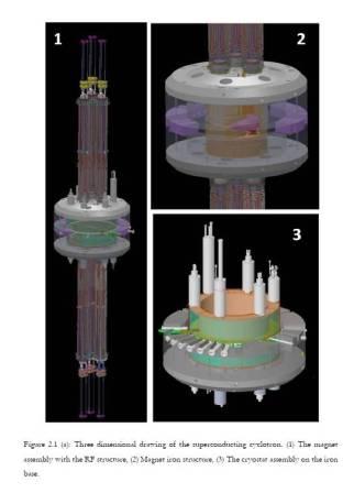
Superconducting cyclotron is a charge particle accelerator, which is generally used to accelerate heavy ions up from Fermi energy to a few hundred MeV/u. The main component of a compact superconducting cyclotron is a pill-box type dipole magnet, with a cylindrical iron structure energized by superconducting Nb-Ti coil, operating at liquid helium temperature (4.2 K). It produces high magnetic field (from 3 to 5 Tesla) to bend the charge particle beams in a near-circular orbit, which spirals out as energy of the beam increases. The energy is given to the beam by radiofrequency electric field produced by RF resonating cavities and electrodes, conventionally called as ‘dees’. At the outermost orbit the beam is pulled out of the cyclotron by electrostatic deflectors and magnetic channels. Being a compact, economic and versatile tool, the superconducting cyclotron finds applications both as machines for nuclear physics research, where flexibility of the machine in terms of various ions and ion-energies are important, and as fixed energy, fixed ion medical cyclotrons.
The superconducting cyclotron has four major components: the magnet iron structure, the cryostat housing the superconducting coils, the trim coils, and the radio-frequency (RF) system of which the three dees are a part.

Superconducting Cyclotron Structure:
Magnet Iron Structure:
The magnet iron comprising of two poles, the lower and the upper, and the return yoke is a pill-box type of structure weighing about 80 Tons. Each of its 0.654 meter radius poles has three spiral hills, each covering an angle of 46° at the outer radii. The average spiral constant is (1/33.02) rad/cm. The poles having hill-valley sectors are installed on two end-plates (top and bottom) that form a part of the return yoke. The gap between the upper and lower hills is 64 mm. The pole gap is much larger (varies radially in three steps, details given in chapter 3) in the three spiral valley regions situated between adjacent hills. This hill-valley structures create the necessary azimuthal variation of the magnetic field. The cylindrical iron return yoke extends from 1.066 meter radius to 1.524 meter radius. The whole structure has a median plane reflection symmetry. The magnet iron frame is installed on pier supporting system, leveled within an accuracy of 800 μm.
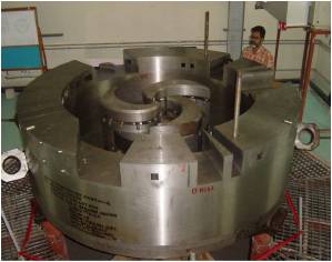
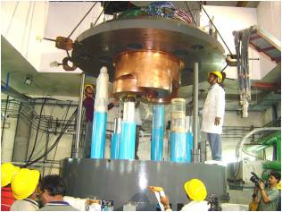
Magnet Yoke SCC Magnet with Cryostat Superconducting Coil and Cryostat:
The cryostat sitting in the annular space (0.654 meter radius to 1.066 meter radius),between the pole and the return yoke houses the superconducting coils, usually referred to as main coils. The superconducting coils are wound on a bobbin made from stainless steel (SS316L). The coils are made of NbTi multifilament composite superconducting cable consisting of 500 filaments of 40 micron diameter embedded in copper matrix. There are two independently powered coils, namely the alpha coil and the beta coil. The liquid helium chamber is created by welding an annular SS sheet to the top and bottom edges of the bobbin all along the periphery ensuring space for enough quantity of liquid helium necessary to cool down the alpha and the beta coils to 4.2 K and for cryogenic stability. The liquid helium chamber is wrapped with several layers of multi-layer insulation (MLI) sheets and outside it there is liquid nitrogen (LN) cooled thermal shield made of copper sheet. There are several layers of MLI wrappings outside the LN-shield also. The entire coil assembly (the liquid helium chamber and the Cu thermal shield wrapped with MLI layers) is then inserted into the cryostat vacuum chamber (coil-tank).The bobbin is kept suspended inside the coil-tank with the help of nine glass-epoxy support-links. Positioning of the bobbin/coil is done by adjusting the tension in these nine support links. There are 20 radial penetrations welded on the outer surface of coil-tank at the median plane. These radial penetrations are used for inserting the drives for electrostatic deflectors and magnetic channels, beam diagnostic elements etc. Cryogenic lines and the power feedthroughs are connected from the top. To access the cyclotron beam chamber one needs to raise the upper half of the magnet.
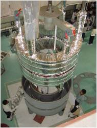
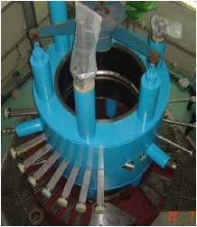
The superconducting coil and liquid nitrogen cooled thermal shield The cryostat assembly with median plane ports Trim coils:
There are 13 trim-coils wound around each spiral pole-tips, below and above median plane. All these 78 trim coils are made of water-cooled copper conductor. The current leads of these trim coils come out through cicular holes in the pole-base and pole-cap. The upper and lower pairs of a particular trim-coil in all three sectors, i.e., six trim coils at a particular radius are connected in series. Trim coil 1 and 13 can be used to produce harmonic fields other than their natural 3N harmonics (N=3) and average field contribution. There is a circular trim coil at the center of the magnet, called trim-coil #0, mounted on the central-plug.The trim coils are mounted on the pole tip and then vacuum impregnated with epoxy resin.
Radio-Frequency System and Dees:
The radiofrequency system comprises of three half-wave co-axial cavities made of copper, placed axially (vertically) with an angular distance of 120° between them. In this structure, the dees and the dee stems act as the inner conductor and the liner on the pole and the hexagonal panels as the outer conductor. The half-wave cavities are actually combinations of two quarter wave cavities, one coming from the top and the other from the bottom and symmetrically placed around the cyclotron median plane. The quarter wave transmission lines’ inner conductors are terminated in three spiral Dees, each of 60° aziumthal width, situated in the three spiral valley regions. Portions of the cavities that extend out of the magnet iron in the axial direction above and below are separated from the cyclotron vacuum chamber by cylindrical ceramic windows. When the particle revolution frequency and the RF frequency match, the ions get accelerated once while entering a dee and again while leaving the same dee. The RF system is designed for a maximum dee voltage of about 100 kV and for a frequency range from 9 to 27 MHz that is achieved by moving a sliding short provided in each of the six quarter wave cavities.
Publication
1. Malay Kanti Dey, Anjan Dutta Gupta, Alok Chakrabarti, “Novel Compact Superconducting Cyclotron for Medical Applications”, Physical Review Special Topics-Accelerators and Beams, 16, 040101 (2013).
2. Tanushyam Bhattacharjee, Malay Kanti Dey, Partha Dhara, Suvodeep Roy, Jayanta Debnath, Rajendra Balakrishna Bhole, Atanu Dutta, S Pal, Amitava Roy, Gautam Pal and Alok Chakrabarti, “Development of a fast scintillator based beam phase measurement system for compact superconducting cyclotrons”, Review of Scientific Instruments, 84, 053303 (2013).
3. Malay Kanti Dey, Anjan Dutta Gupta and Alok Chakrabarti, “Design of ultra-light superconducting proton cyclotron for production of isotopes for medical applications”, Proceedings of the 20th International Conference on Cyclotrons and Their Applications, 16-20 September 2013, TRIUMF, Vancouver, Canada.
4. Malay Kanti Dey, Rakesh Kumar Bhandari, et. al. “Beam Tuning in Kolkata Superconducting Cyclotron”, Proceedings of the 19th International Conference on Cyclotrons and Their Applications, 6-9 October 2010, Lanzhou, China.
5. Malay Kanti Dey, Rakesh Kumar Bhandari et al., “Beam Injection System of the Kolkata Super-conducting Cyclotron”: Proceedings of the 18th International Conference on Cyclotrons and Their Applications 2007, Oct. 1-5, 2007, Giardini Naxos, Italy, page 346.
6. Malay Kanti Dey, Rakesh Kumar Bhandari, et. al., “Coil Centering of the Kolkata Superconducting Cyclotron Magnet”: Proceedings of the 18th Int. Conf. on Cyclotrons and Their Applications 2007, Oct. 1-5, 2007, Giardini Naxos, Italy, page 438.
7. Chaturanan Mallik, Malay Kanti Dey, Rakesh Kumar Bhandari, et al., “Magnetic Field Mapping of Kolkata Superconducting Cyclotron”: Proceedings of the 18th Int.Conf. on Cyclotrons and Their Applications 2007, Oct. 1-5, 2007, Giardini Naxos, Italy, page 435.
Cyclotron Operation Section
Overview
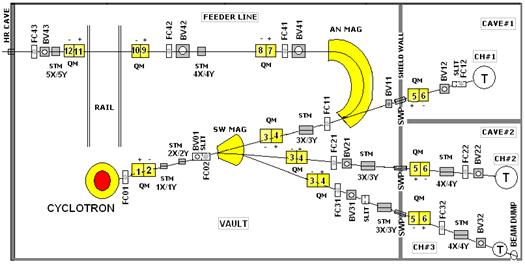
Cyclotron operation section is primarily responsible for producing the beam of a variety of ions of various energies and transporting this beam to the target sample as per the requirement of the experimentalists. Various operational parameters are required to be tuned at the control consol for acceleration of a beam specified by its final energy and charge to mass ratio. Apart from delivering beam on target, cyclotron operation personnel keep a close monitoring of all sub-systems and make good quality coordination among the system personnel in shift duty operation for smooth functioning of cyclotron.
Cyclotron operation section is engaged in the development of new beam in terms of beam energy and beam current and also involved in the up-gradation and modernization activities of the cyclotron.
Cyclotron operation personnel are demonstrating the cyclotron systems to the students from various institute of all over India and describing the role of it to scientific research and to the society.
The K-130 room temperature cyclotron after having accelerated light heavy ion beams from 1997 to 2007 was shut down for implementing large scale changes under the “Modernisation of VEC Technical Systems” project. The cyclotron operation was stopped in March 2007 after having completed the successful run of Indian National Gamma Array (INGA) with the heavy ions. During shutdown the major changes related to modifying subsystems which were either failing frequently or because their maintenance was posing too many difficulties. Some of the works related to relocating the existing systems or building new facilities.
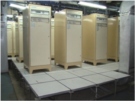
Some of the major up-gradation and modification works are:a) The magnet power supplies (Main magnet, Trim coils, Quadrupole magnets, Steering magnets, switching magnet etc.) have been installed at the newly renovated pit area. Vault floor has been epoxy painted.
b) Two new 36-inch gate valves for two main diffusion pumps have been installed which has improved the quality of the vacuum system. Implementation of PLC based control of vacuum system.
c) New Ion Source Power (PIG Ion Source) supply is functioning satisfactorily and it is computer controlled.
d) The relay-based safety interlock system has been up-graded with PLC based safety interlock system connected RF system.
e) All magnet power supplies mentioned above are operated from the control console through computer.
f) The control console went for a major revision incorporating computerized control system for most of the subsystems.
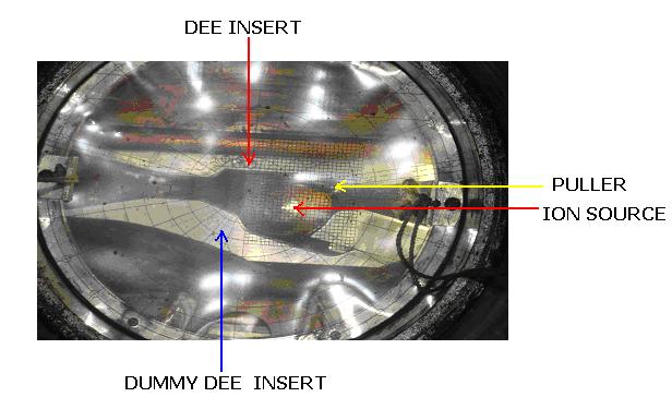
g) New Deflector power supply is functioning satisfactorily and it is also computer controlled. h) Central region of the cyclotron has been modified to make it compatible with internal PIG ion source
i) Air conditioning system has been upgraded at vault and pit area.
j) Major modifications in Low Conductivity Water system and the Electrical system had to be carried out to incorporate above changes.
k) Building new vacuum chamber for the 160 degree analyzing magnet and energization of feeder beam line for transporting beam to the Radioactive Ion Beam Facility.
l) Re-commissioning of existing High Resolution beam line, presently known as ‘feeder beam line’, for transporting beam to the Radio-active ion beam facility. Other three beam lines have also been modified and upgraded with new beam diagnostics.
Synchronization: The volume of work was large and some unforeseen problems did crop up during implementation. Finally all the systems were energized in November 2009. First internal beam with the new setup was obtained in December 2009. On January 10, 2010 external beam was obtained. Experiment started in channel #1 on 8th February 2010. Since then the cyclotron continues to deliver beams of alpha and proton on the targets.
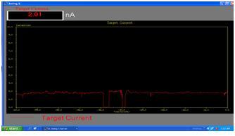
Beam stability: Following picture shows extracted beam and the stability of beam current on target as function of time. Time scale (horizontal) is for 60 minutes. Current scale (vertical) is for 10 nA. Two dips in the middle occur due to drop of deflector voltage but returns back within a minute automatically.
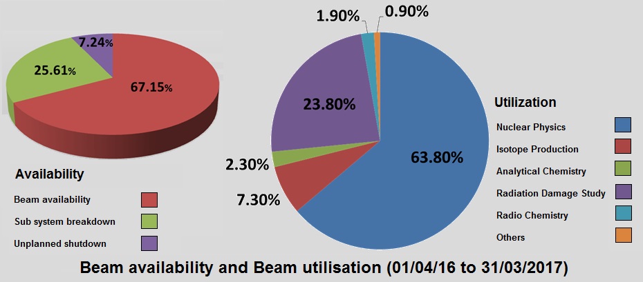
Beam availability and utilisation is shown in pie chart
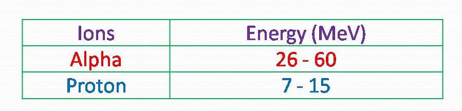
Projectiles: At present the following ions with beam energy and beam current are available from K-130 cyclotron for performing experiments.
Experiments performed: The above beams are being used extensively in various fields of research mainly in nuclear physics in channel #2 and #3, radio-chemistry and material science in channel #1 and producing of radio-active atoms in feeder beam line.
Experimentalists: The research work with the above beams has been performed by experimentalists of VECC, Saha Institute of Nuclear Physics, BRIT/VECC, RchD/BARC, RPhD/BARC, AChD/BARC, MMD/BARC, UGC-DAE-CSR and Kyungpook National University, Korea.
Cyclotron Control Section (Conventional)
Overview
In the cyclotron, radio-activity is associated with the production of high energy charged particle beams, necessitating the operation of the accelerator through remote control. To protect the personnel and the environment from radio-activity, the 'vault' housing the cyclotron and the experimental 'caves' have biological shields of thick concrete walls around them. 'S' shaped bends are embedded in these shield walls to carry all the services like power cables, signal cables, water and air lines etc. in and out of the vault and cave areas.
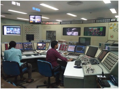
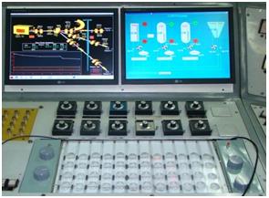
A number of electrical and mechanical interlocks are in place for the safe operation of the cyclotron. For controlling all the equipments and services required for operating the cyclotron and optimizing various parameters, an extensive remote control system is used. Most of the conventional control systems are located in the control room which is situated outside the biological shield. The control console in the control room has switches for all the power supplies like main magnet, radio frequency system, ion-source, deflector and other magnet power supplies etc; their controls and read outs for setting voltages or currents, emergency trip buttons, alarm annunciation system buttons, current integrators, frequency synthesizer, push buttons for gate-valves, faraday cups, beam viewers, shield wall plugs etc. Behind the console there are control panels equipped with beam viewers, CCTV monitoring, computerized monitoring of vacuum system and computer control system, radiation monitoring system, beam line vacuum operation and control system, alarm annunciation units , deflector model etc. In addition to these controls located in the control room, there are local inspection stations, emergency shutdown buttons, emergency door opening buttons for vault, pit and cave areas and local door control panels for normal opening and closing of the shield doors are also present.
Vacuum Section
Overview
1. Introduction:
Vacuum team pursues various upgrade programs of the next-generation vacuum system for K-130 and Superconducting Cyclotron, beam transport line, SCC injection line to improve the accelerator performance and operation efficiency. Our main aim is to have operation of vacuum system for achieving a good quality vacuum in all vacuum spaces used for acceleration and beam transport. The high vacuum is a basic requirement for acceleration of charged particles in an accelerator to avoid high voltage R.F. breakdown as well as to prevent particles losses due to molecular collisions with residual gas. High vacuum production is major challenge to achieve especially in large acceleration chamber of Variable Energy Cyclotron (VEC) as well as in complex system of Superconducting Cyclotron (SCC) of this centre. Theoretical consideration and practical experience show that a pressure in range of 5 x 10⁻⁶ Torr – 1 X 10⁻⁵ Torr for VEC and ~1 X 10⁻⁷ Torr for SCC provide reliable operation and prevent RF breakdown. Vacuum group is involved in activities of the following vacuum systems.2. K-130 cyclotron vacuum systems:
2.1. Cyclotron vacuum systemThe vacuum systems for K-130 cyclotron consist of RF chamber, acceleration chamber and beam transport line. The cyclotron vacuum chamber comprises a stainless steel acceleration chamber i.e. dee tank and RF chamber i.e. resonator tank made out of mild steel and copper cladded steel. The combined volume of resonator and dee tank is nearly 23 m3.The resonator tank has two 889 mm openings at the bottom to which a pair of assemblies comprise of 889 mm oil fractionating diffusion pumps having speed of 42000 l/s, refrigerated chevron baffle and electro-pneumatically operated high vacuum gate valve is attached. For the evacuation of the entire system from the atmospheric to few microns before main diffusion pumps are valved, a powerful roughing system comprising roots and rotary mechanical pumps has been installed. Apart from above combination of pumping system, a 30 cm oil diffusion pump of 2000 l/s pumping speed with integrated gate valve and baffle has been also installed on the Dee Tank close to the accelerating region to provide extra pumping. The average pressure 2-3 x 10⁻⁶ mbar without beam and 4-5 x 10⁻⁶ mbar with beam is achieved.
2.2. Beam line vacuum system:The beam transport line has three channels for experiments. Its combined length is around 58 meter. The beam line connects dee chamber at extraction port in the level of beam line experiments. The beam transport line is made of Aluminum tube and stainless steel dipoles and diagnostic chambers. The entire beam line is pumped down with 19 pumping stations. Each pumping station is combination of oil diffusion pump, rotary pump, gate valve and gauges. The average pressure ~ 5 x 10⁻⁶ mbar is achieved regularly inline.
3. SCC vacuum system:Superconducting Cyclotron needs very high vacuum in major vacuum spaces like cryostat outer vacuum chamber (OVC), acceleration chamber i.e. beam chamber, liner chamber, beam line and injection line. Considering the varying requirement of vacuum level in spaces according to necessities and their operational constraints, these spaces are evacuated with independent vacuum system.
3.1. Cryostat Outer Vacuum chamber or the Cryostat (OVC) Vacuum SystemCryostat has an annular space between the inner liquid helium container (the stainless steel bobbin) and the outermost container (known as coil tank) also called cryostat outer vacuum chamber (OVC). The pressure in the vacuum space is less than 10-5 mbar during operating state.
Two pumping system, a Turbo molecular – scroll pump combination, are used alternatively / simultaneously to maintain vacuum level less than < 1.0 x 10⁻⁵ mabr. Considering the influence of magnetic field on vacuum gauges and turbo pump, pumping units are placed about 3600 mm below the median plane.
3.2. Beam chamber vacuum system:Beam chamber i.e. the space between upper liner, lower liner and coil tank, is also known as acceleration chamber where charge particles are accelerated in cyclic orbits. This chamber is evacuated with three turbo molecular pumps and each backed by scroll pump. The net pumping speed for all three pumps together is about 150 liter/sec. For evacuation of beam chamber from atmosphere to ~ 5.0 x 10⁻² mbar, there is one main roughing port which is connected to the backing pump used for the turbo pump through an electro-pneumatic isolation valve. Subsequent pumping is carried out with three turbo molecular pumps to achieve pressure in the acceleration chamber below 10-6 mbar. At last, three cryopanels are operated to achieve pressure in range of 10-8 mbar. Each cryopanel is made of OFE C10100 copper and the liquid helium cooled panel is surrounded by liquid nitrogen cooled chevron baffles. The three Cryopanels together provide a pumping speed of 6000 liter / sec. for air.
3.3. Liner vacuum systemThe space between the upper liner and the upper magnet iron elements within the cryostat inside diameter forms the upper liner vacuum space. Similarly, the space between the lower liner and the lower magnet iron elements within the cryostat inside diameter forms the lower liner vacuum space. Epoxy impregnated trim coil assemblies on the magnet pole tips lie within the liner 'vacuum' spaces. A low quality vacuum is adequate in the liner vacuum space.
A set of two oil sealed rotary pumps with interlocked valves, one of them as stand-by, assures the availability of pumping. There are three vacuum ports available for each of the two vacuum spaces. Two ports each of the two spaces are connected to a common header.
3.3. Beam transport line vacuum systemBeam line connects the cyclotron through extraction port to transport energetic particle beams to the designated destinations in the caves for experiments. There are a variety of intricate elements for beam diagnostics, beam viewing, bending and focusing along the lines having path length of about 20 meter.
Distributed pumping has been provided between any two major elements / on a diagnostic element along the beam line. Also, at least one pumping station is used between two isolation valves. Initial evacuation from atmosphere to ~ 5.0 x 10⁻² mbar is done using backing pump. Subsequent pumping is done directly through turbo pump port to attain pressure around ~ 1.0 x 10⁻⁷ mbar. All the demountable ports are CF flanges with OFE copper gaskets.
3.4 SCC injection line vacuum systemInjection line is used to transport low energy beam from ECR ion source to center region of superconducting cyclotron. This is around 18 meter long and comprises of stainless steel tubes, diagnostic and dipole chambers. Injection line is evacuated by three turbo molecular pumps backed by scroll pumps and three cryopumps installed along the injection line. The average pressure ~ 3.0 x 10⁻⁷ mbar is maintained along the line to transport low energy beam.
ECR ION SOURCE FACILITY SECTION
Overview
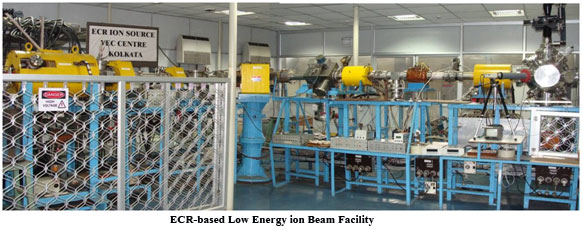
6.4 GHz ECR ion source (ECR I) based low energy ion beam facility at VECC:
Low energy ion beams provide a controlled means for modifying material surfaces for the achievement of desired properties. Such ion beams have ranges of few tens of nanometers in most of the materials and hence are suitable for surface modification studies. A unique, low energy heavy ion irradiation/implantation facility has been developed at VECC for materials science and atomic physics research. The facility utilizes the indigenously developed 6.4 GHz ECR ion source, which was earlier being used to inject heavy ions into the room temperature cyclotron at VECC. Fundamental and technologically important problems of materials science and atomic physics can be studied with the positive ion beams available from this facility over a broad range of high charge state species like N, O, Ne, Ar, Kr, Xe, Fe, Ti etc. It can deliver ion beams up to a few micro amperes at an energy of 10 keV per charge state, enabling to generate high defect densities i.e. high value of displacement-per-atom (dpa).
The ion beam is focused to a spot of about 2 mm diameter on the target using a set of glaser lenses. AX-Y scanner is used to scan the beam over a target area of 10mm x 10mm for uniform implantation. The sample chamber has provision for mounting multiple samples on indigenously developed disposable type beam viewer for in-situ beam viewing during implantation.
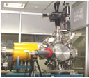
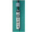
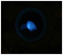
Implantation chamber with sample manipulator Beam spot on viewer Target Ladder Assembly To meet the requirements of the material scienists, ion beams of S, Fe, Ti and Hf have also been developed using the MIVOC technique. In this method, the ion source feedmaterial usually is a high vapour pressure compound containing desired element. It has been observed that to obtain good yield the vapour pressure of the compound should lie between 10 to 0.1 Torr at room temperature. A dedicated set up has been developed for this purpose which has the pumping and vacuum measuring facility of its own. The MIVOC setup is electrically isolated from the ion source enabling its operation at ground potential. The vapour of the MIVOC compound is injected into the ion source using an electro-mechanically operated sapphire seal valve. With this arrangement it is possible to optimize the ECR parameters for the desired ion species. It has been observed that for certain ion species a suitable mixing gas is essential for improving the required beam yield.
14.45 GHz ECR ion source (ECR II) based heavy ion acceleration with K500 Superconducting Cyclotron at VECC:
Electron Cyclotron Resonance Ion Source (ECRIS) is an ion source that produces high current high charge state ion beams of almost all elements in the periodic table. Plasma is created in a chamber with the aid of microwave power. Permanent magnets and electromagnets are used to confine the plasma where the electrons gain energy by absorbing microwave power resonantly. Magnets are arranged in such a way that electrons are reflected from the edges of volume plasma towards the centre where the magnetic field is week. Electrons and ions have long life time in the plasma and hence undergo large number successive collisions and form high charge state ions. Several processes for ionization takes place in the plasma chamber at the same time. Out of many the electron – neutral, electron – ion, ion-neutral, ion-ion collisions are the major ionization processes that take place in the ion source. Microwave power, gas pressure and magnetic field profiles in the plasma chamber are the control knobs to change the charge state distribution in the ECR ion source.
Energy of the ions after acceleration in cyclotron is proportional to square of the charge state and hence higher the charge state of injected ion beam, higher is the energy gain by ions in the cyclotron.
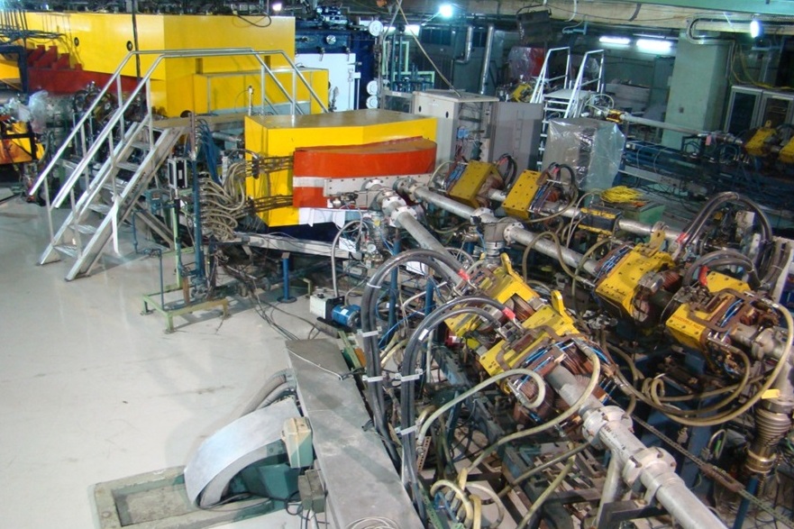
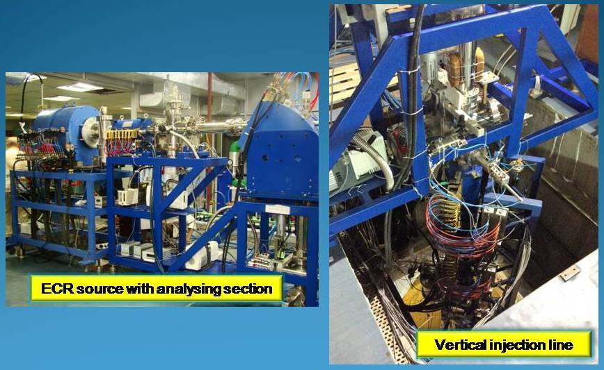
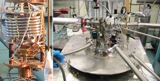
An ECR (ECR-2) ion source operating at 14.45 GHz is installed to produce ion beams and inject into the cyclotron. Figure 1 presents a view of the ECR ion source where microwave injection system, water cooling lines etc can be seen.
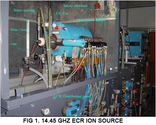
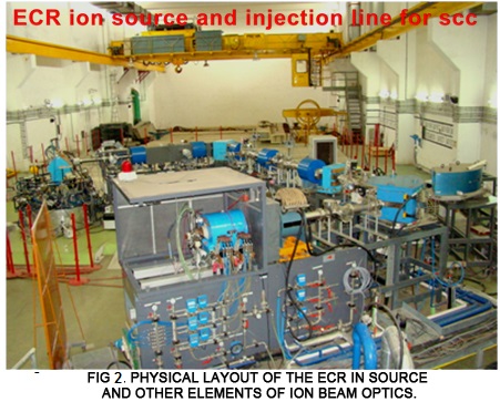
Figure 2 shows the physical layout as it exists on high-bay area. Ion beam extracted from ECR ion source is mass analyzed and bent twice to inject into the cyclotron. There are several optical elements such as Glazer lenses, bending magnets and steerers. There are a host of beam diagnostic elements such as Faraday cups and collimators distributed through-out the beam line. Three gridded ion beam buncher is installed in the vertical injection line to enhance the efficiency of injection and acceleration.
Control system of ECR ion source follows a distributed architecture to reduce enormous cabling and to improve the reliability. All parameters are controlled and monitored from one single computer placed in ion source hall of high-bay. In addition, all the parameters can also be controlled from another terminal in the main control room of superconducting cyclotron. Figure 3 shows the view of control room.
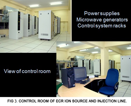
Figure 4 is the typical control panel of the ion source and injection line parameters. The page has tab controls and each tab is meant for control and monitor of particular group of parameters, e.g, first tab is for ion source control, second tab is for injection line control, third tab is for vacuum system control. The control system is developed in such a way that the ion beam from faraday cup and collimators can be observed on any page. This feature is very important because the ion beam position and profile down the beam line are affected by any optical elements placed upstream of the Faraday cup.
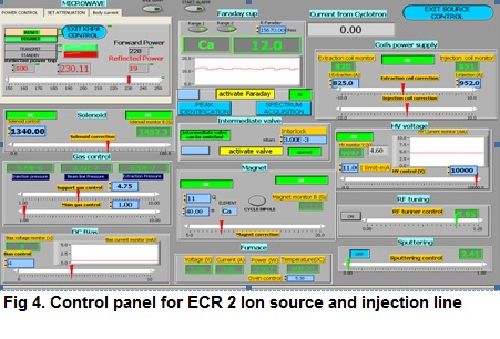
Control software also has a feature to continuously log the data and save the latest parameters for quick restart of the system in case of the power failures.
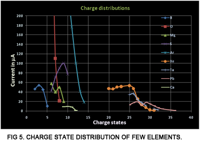
Sevearl ion beams have been developed and few of them are listed below in graphs shown in figure 5. Ion beams of solid elements are produced by using micro-oven and by sputtering method depending on the vapor pressures of different elements.
14.45 GHz ECR ion source (ECR III) based heavy ion acceleration with K130 Cyclotron at VECC
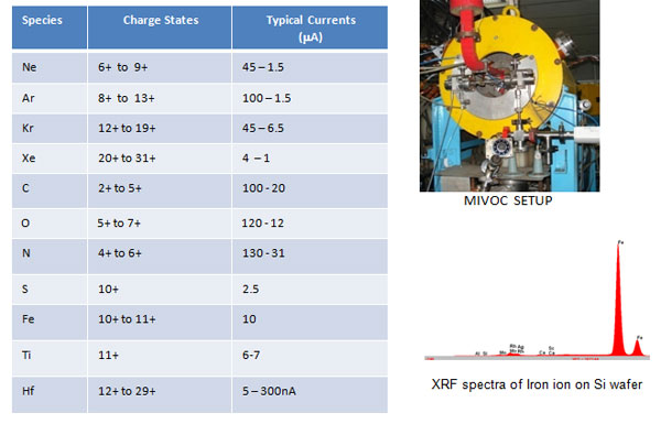
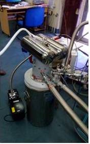
As a part of the heavy ion acceleration program with K130 room temperature cyclotron the 14.45 GHz. ECR source (ECRIII) produces multiply charged heavy ions and injects them into room temperature cyclotron for further acceleration.Figure 6 shows the ECR III source along with the injection beam line.
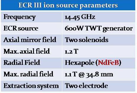
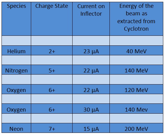
Following table shows the ECR source parameters.
Following image shows the Spectrum of different samples as obtained from ECR 3.
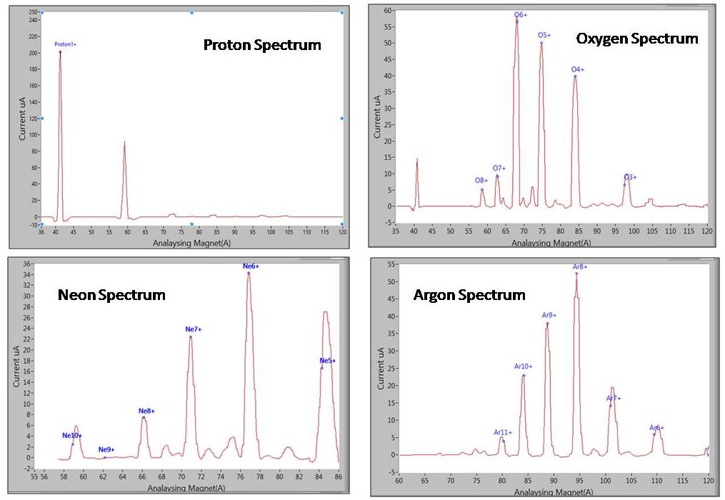
Typical beam currents as obtained from ECR 3 for acceleration in Room Temperature Cyclotron.
Publication
Helium Technology and Low Temperature Section
Overview
Major activities
1. Dilution Refrigerator
Dilution refrigerator is a device that can achieve and maintain continuous refrigeration in the milli-Kelvin temperature range with substantial cooling power. It takes advantage of the unique low-temperature behaviour of the 3He-4He mixtures below about 0.87K producing phase separation between two isotopes. A lighter and rich in3He called concentrate solution floating on top of the 4He rich phase called dilute solution respectively. In order to maintain the finite solubility of 3He in superfluid 4He, the lighter 3He atoms cross the phase boundary over to dilute solution below results in cooling.Recently, we have indigenously designed, developed and tested a dilution refrigerator for producing milli-Kelvin temperature. The base temperature obtained was below 50mK in the mixing chamber.
Initially, the project was aimed at developing technologies relevant to dilution refrigerator so each component were designed, fabricated and tested in the laboratory. In this context, we have developed a computer programme SIDFO for initial design and optimization of dilution refrigerator as it greatly reduces the risk of serious design flaws. The infrastructure specific to very low temperature work has been developed for the purpose. Efforts to achieve still lower temperature would be on since low temperatures allow study of quantum phenomena such as superfluid phase transition of 3He, quantum hall effect,semiconductor-based nano-materials, low temperature detectors superconducting tunnel junctions, low temperature nuclear orientation and NMR experiments and so on.
2. Development of Cryogen-free cryostat for Recondensation of helium vapour
A small scale 4He liquefier has been designed and constructed that is solely based on the cooling of a two-stage 4K pulse tube cryo-cooler. In a further expansion a cryogen-free super-fluid cryostat with closed loop helium circulation system is under development. This cryostat is uniquely qualified to provide the cooling requirement along with an option for magnetic field for materials research, neutron scattering, NMR studies etc. for many branches of physics. Unusual phases of matter such as superconductivity at low temperatures and much subtle behaviour of materials that are obscured by thermal motion at relatively higher temperature can be studied in great detail low temperature regime (~ 1.8 K). The closed cycle super-fluid cryostat will be extremely useful to the experimental nuclear physics community. Some of the very central research areas involve MRI, NMR and SQUIDs. Its usefulness arises from the fact that it operates continuously, it can provide a substantial cooling power along with a magnetic field at temperatures from around 1.8 K and it can run uninterrupted for as long as several months. Most existing superconducting systems employ a liquid helium refilling system that is costly, troublesome and must be maintained by a skilled technician. To replace the standard refill system with helium re-condenser presents a challenge.
Publication
Medical Cyclotron Section
Overview
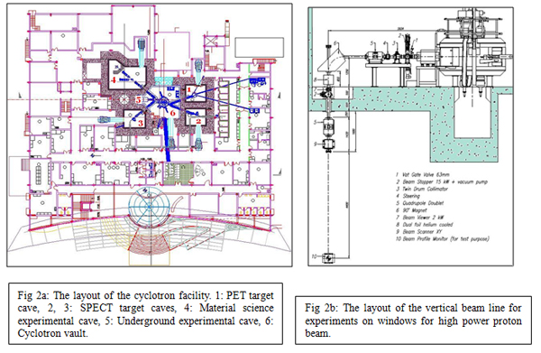
Cyclotrons are now one of the most popular commercially available accelerators customized in medical and industrial applications, apart from its use in atomic, nuclear and solid-state physics research. More than hundred cyclotron are engaged worldwide in the production of PET and SPECT isotopes (11C, 13N, 15O, 18F, 123I, 203Tl, 67Ga) used in medical diagnostics, including isotopes for therapeutic applications too, e.g., 64Cu, 103Pd, 186Re etc. In India the reactor produced radio-pharmaceuticals have been routinely used by the nuclear medicine centers for long time. Few low energy cyclotros have also been running for some time in Mumbai, Delhi, Bangalore and Hyderabad, producing PET radioisotope and 18F labeled Fluoro-Deoxy-Glucose (FDG). However, there is increasing demand for SPECT isotopes, 201Tl, 123I, 111In, 67Ga etc., which have advantage of longer half life, hence taking care of the transportation time from the production facilities to the diagnostic centers. All these radioisotopes require higher beam energy and intensity for their profitable production. Therefore, a 30 MeV 500μA proton cyclotron facility is being set up by the Department of Atomic Energy at Kolkata. This high current cyclotron will be used to produce PET (Positron Emission Tomography and SPECT (Single Photon Emission Computed Tomography) isotopes for medical diagnostics purposes. At the same time, there will be provision for front-line research experiments in the fields of material sciences, radiochemistry, liquid metal target development etc.
The facility is based on a high current cyclotron (Cyclone-30) and five beam lines, procured from M/s IBA, Belgium. Two proton beams will be simultaneously extracted from the cyclotron. The beams can be of different energy and intensity. There will be several beam lines for utilization of the beam. Two beam lines are being dedicated for SPECT and one for PET isotope production. In addition, there will be one dedicated beam line for material science and chemistry research. A fifth beam line, which will bend the beam vertically down into a basement cave, will be utilized for dedicated experiments for R&D on windows for high power beams. Several hot cells will be provided for SPECT and PET isotope radiochemistry works. In addition, several hot cells will be provided for research experiments also. This facility will offer unique opportunities for R&D in the area of radiochemistry, material science, isotope production and their applications.
CYCLOTRON SYSTEM LAYOUT
Isotope
(T1/2 hrs)Nuclear Reaction Proton Energy (MeV) Beam Current (A) Ga-67
78.368Zn(p, 2n) 67Ga 28.5 200*
Tl-201
73.5203Tl(p,3n)201Pb, (9.4h)
201Pb (EC/+) 201Tl28.5 200* In-111
67.9112Cd(p,2n) 111In 28.5 200* FDG
1.818O(p, n) 18F 18 40 Nuclear reactions responsible for the production of relevant radioisotopes along with the beam energy and current required for these reactions, are listed in Table-1. The required proton beam energy to cover all the reactions varies from 18 MeV up to 28 MeV and beam current varies from 40 up to 200 A. Cyclone-30 is a negative hydrogen ion cyclotron, but positive proton beam is extracted from it. The negative hydrogen ion beam, produced in an external cusp ion source, is axially injected into the cyclotron. Two RF cavities accelerate the negative ions. At extraction radius carbon stripper foils are used to extract two simultaneous proton beams from the machine. The extracted beam energy is adjustable from 15 MeV up to 30 MeV and the beam current is tunable up to 500A. High beam quality is ensured, giving horizontal emittance <10-mm-mrad and vertical emittance <5-mm-mrad.
The facility will have two beam lines on one side and three on the other side, as shown in fig. 2a. Two beam lines will be used for irradiating solid targets (Ga, Tl), one for PET targets and rest of the two beam lines will be used for various R&D experiments. There will be two automated solid target irradiation systems, for the production of 67Ga, 201Tl (optionally 123I, 111In) and one automated gas/liquid target irradiation system for the production of [18F] fluoride, [18F]F2, [11C]CO2, [15O]O2 etc. After irradiation, the solid targets will be transported to the receiving hot-cell via pneumatic transfer system. A fully automated radiochemistry system will be used for the remote production of labelled molecules from the irradiated target
The third beam line will be bifurcated in to two chambers to carry out material science experiments depending on the energies and currents to be utilized for irradiation. The straight beam line will be used for high dose experiments (200uA). There will be a vertical beam line (fig. 2b) to use full beam power (15 kW) on the target, to carry out following experiments: window thermal-cycling studies in LBE target flow conditions, active gas handling techniques, remote handling of irradiated target, radiation damage studies in the materials for target window and other subsystems.
R&D IN MATERIAL SCIENCE : High intensity proton beams from the Medical Cyclotron Section provide a unique facility for radiation damage studies on reactor materials, as energetic charged particles are useful for simulating the bulk damage induced by fast neutrons. For example, 20 MeV protons with 350 μA current will produce, in stainless steel, a damage of 2x10⁻⁵ dpa/sec over a sample thickness of about 0.7 mm. This is higher than the damage rate produced in fast reactors (~10-6 dpa/sec). With this energy, thick samples of the order of 0.5 to 1 mm can be irradiated. This makes the post irradiation investigation of the samples feasible by a variety of bulk techniques like XRD, positron lifetime, mechanical property measurements. The main interest will be in studying the irradiation effects in structural materials like D9, D9I and ferritic steels. Some of the important studies that will be carried out are: ductile to brittle transition in ferritic steels, development of void swelling resistant steels, phase stability under irradiation in advanced austenitic steels etc. Apart from radiation damage studies on nuclear structural materials other areas of experiments in the material science beam line will include induced radioactivity studies, thin layer activation analysis of nano-coatings, production of special isotopes for use as sources in various experiments like PAS, PACS etc., study of mass, charge and angular momentum distribution of fission products in proton induced fission of actinides etc. Studies on basic damage mechanisms are of importance for better understanding of radiation effects in materials will also be carried out using this facility. For example, in the ordered intermetallics, the evolution of disorder and amorphization during irradiation is of fundamental interest. Another class of materials in which defect accumulation and consequent amorphization is of interest is ceramics used for nuclear waste disposal. The availability of high-energy beam will facilitate the study of the damage phenomena in these materials using a wide variety of bulk techniques such as XRD and positron lifetime.
For effective utilization of the proton beam, there will be two beamlines in the Materials science Cave, one for high dose experiments (where high currents for long duration will be used) and another for low dose experiments (where low currents for short duration will be used). The fig. (3) shows the two beamlines inside the cave. The beam will be delivered to either of the beamlines using the switching magnet. The high dose experiments will be carried out in Sub beamline1. Because of the high irradiation dose expected to be produced in the samples, the irradiation facility will be surrounded by a shielding wall (shown in the fig.) and the sample will be removed from the target holder remotely using a Master-Slave manipulator and loaded into a Pb-cask for storage until the activity decreases below the permissible limit of handling. The low dose experiments will be carried out in Sub beamline 2 and the activity will be kept below the permissible limits.
Proper utilization of the beam energy and beam current requires the careful development of irradiation facility including the target chamber, target cooling facility and post-irradiation target handling facilities. The high energy of the proton restricts the use of common materials (usually Fe based), near and around the target. Hence a reasonably large specialized infrastructure has to be designed to enable maximum utilization of the facility. The Materials Science beam line irradiation facility at the DAE Medical Cyclotron Section will include the following special features.
(1) A General purpose target chamber made of Aluminium to reduce the induced activity in the chamber. The chamber will include various facilities such as non-contact temperature monitors (IR Pyrometers), Radiation resistance camera to view the sample, a graphite coated beam dump to collect the beam behind thin samples etc. among others. (The schematic of the target chamber is shown in Fig.
(2) Provision for sample cooling by Helium gas. The arrangement will provide Helium gas in closed loop with heat exchanger facility.
(3) Provision for water cooling arrangement.
(4) Remote sample handling facility including Master Slave manipulators to remove sample from the target holder and transfer into a lead cask.
(5) Monorail arrangement for transferring the lead cask to outside the cave etc.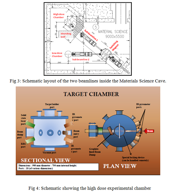
Beam Extraction and Beam line
| Article | Author | Journal/Symposium | Year |
| Magnetic Field Mapping of Kolkata Superconducting Cyclotron | Chaturanan Mallik, Malay Kanti Dey, Rakesh Kumar Bhandari, et al | Proceedings of the 18th Int.Conf. on Cyclotrons and Their Applications 2007, Oct. 1-5, 2007, Giardini Naxos, Italy, page 435 | 2007 |
| Coil Centering of the Kolkata Superconducting Cyclotron Magnet | Malay Kanti Dey, Rakesh Kumar Bhandari, et. al | Proceedings of the 18th Int. Conf. on Cyclotrons and Their Applications 2007, Oct. 1-5, 2007, Giardini Naxos, Italy, page 438 | 2007 |
| Beam Injection System of the Kolkata Super-conducting Cyclotron | Malay Kanti Dey, Rakesh Kumar Bhandari et al | Proceedings of the 18th International Conference on Cyclotrons and Their Applications 2007, Oct. 1-5, 2007, Giardini Naxos, Italy, page 346 | 2007 |
| Beam Tuning in Kolkata Superconducting Cyclotron | Malay Kanti Dey, Rakesh Kumar Bhandari, et. al. | Proceedings of the 19th International Conference on Cyclotrons and Their Applications, 6-9 October 2010, Lanzhou, China | 2010 |
| Design optimisation of superconducting magnetic energy storage coil | U. Bhunia, S. Saha, A Chakrabarti | Physica-C, 500 (2014)25-32 | 2014 |
| Pareto-optimal design of sector toroidal superconducting magnet for SMES | U. Bhunia, S. Saha, A Chakrabarti | Physica-C, 505 (2014) 6-13 | 2014 |
| Design of a 4.5 MJ/1MW sectored toroidal superconducting Energy storage magnet | U. Bhunia, J. Akhter, C. Nandi, G. Pal, S. Saha | Cryogenics, 63, (2014), 186-198 | 2014 |
| Design study of 4.5 MJ sector-toroidal SMES coil | U Bhunia, J Akhter, J Pradhan, B Mondal, C Nandi, V K Khare, U S Panda, A De, S Bandopadhayya, A Roy, T Bhattacharyya, S K Thakur, M Das, G Pal and S Saha | Indian Journal of Cryogenics, Vol.38 | 2017 |
| Design of Cryo-refrigerator assisted HTS steering magnet for K500 cyclotron beam line | U Bhunia, Md Z A Naser, T Ghosh, Pankaj Kumar, C Nandi, A Agarwal, C Das, J Pradhan, J Debnath, M K Dey, G Pal and A Chakrabarti | 38 (2017), 110-114 | 2017 |
| Transient stability of Nb-Ti Rutherford cables for energy storage magnet applications | U Bhunia, J Pradhan, A Roy, V K Khare, M K Dey, S K Thakur, H Kanithi | Materials Science and Engineering 171 (2017), 1-7 | 2017 |
| Online quality factor measurement of SRF cavity in Injector Cryomodule in VECC electron linac | U Bhunia, V Naik, R E Laxdal, M. Yanyun, R Nagimov, D Kishi, V. Zvyagintsev | Indian Journal of Cryogenics", 43 (2018), 89-93 | 2018 |
| Study of orbit properties and intense beam dynamics in a high current separated sector proton cyclotron | A Goswami, Atanu Dutta and Arup Bandyopadhyay | Journal of Instrumentation 14 (2019) 3027 | 2019 |
| Design of a spiral inflector and transverse beam matching for K130 cyclotron at the Variable Energy Cyclotron Centre | A. Goswami, Atanu Dutta and Santanu Paul | Pramana - J Phys, 2019, 93, 15 | 2019 |
| Development and Testing of Radio Frequency Modulated Electron Gun at VECC | M. Z. A. Naser, S. Dechoudhury, D.P. Dutta, S. K. Thakur, S. Haque, V. Naik, A. Bandyopadhyay | Journal of Instrumentation (JINST), 14(11), Nov 2019 | 2019 |
| Development of Cost Effective Lab Scale 6 Tesla Superconducting Magnet | V.Ravindra, UttamBhunia, P.N. Vishwakarma, V V Rao, S.K. Sarangi | International Journal Of Engineering Research And Development, 16 (10) (2020), 20-28 | 2020 |
| Characteristics of beam loss in compact superconducting cyclotron | J Pradhan, J Debnath, A Dutta, S Paul, U Bhunia, MK Dey, AD Gupta | JINST, 15, T08006 (2020) | 2020 |
| Optimization of compensation of magnetic field imperfection in K500 superconducting cyclotron | J. Debnath, U. Bhunia, M.K. Dey, J. Pradhan, A. Dutta, S. Paul, A. Dutta Gupta, A. Bandyopadhyay and S. Som | JINST, 15, T09004 (2020). | 2020 |
| Design study of of Superconducting Quarter Wave Resonator for Post Acceleration of Radioactive Ion Beam Facility at VECC | Uttam Bhunia, Arup Bandyopadhyay, Pratanu Chakraborty, ManasMondal, VaishaliNaik, R. E. Laxdal, Z. Yao, B. Waraich, B. Matheson, and E. Glenwright | Indian Jl. of Cryogenics, 45 (1) 64-69 (2020). | 2020 |
| Median plane and Beam Diagnosis in the Central region for Compact Superconducting Cyclotron | J. Pradhan, J. Debnath et al | Nuclear Instruments and Methods in Physics Research Section A, Volume 993, 21 March 2021 | 2021 |
| Effect of solenoid misalignment on the injection efficiency for K500 superconducting cyclotron at VECC | Santanu Paul, A. Goswami, Md. Zamal Abdul Naser, M. K. Dey, A. Bandyopadhyay | Pramana – J. Phys. Volume : 96, Page No. : 160, MONTH-YEAR : 8-2022 | 2022 |
| Beam based diagnostic and four dimensional transverse emittance measurement using solenoid scan for 100 keV thermionic electron gun at VECC, Kolkata | Siddhartha Dechoudhury, SanketHaque, Md. Zamal Abdul Naser, Shourya Mukherjee, Arihant Kumar Jain and VaishaliNaik | JINST, Volume 17(06), June 2022 | 2022 |
| Beam Dynamics Simulation Study for Longitudinal Bunch Length Measurement of RF Modulated Thermionic Electron Gun at VECC, Kolkata | M. Z. A. Naser, S. Dechoudhury, D.P. Dutta, D. Hazra, V. Naik, A. Bandyopadhyay | Journal of Instrumentation (JINST), Volume 17, Feb 2022 | 2022 |
| A beam dynamics study for efficient extraction from the VECC K500 superconducting cyclotron | S. Paul, U. Bhunia, J. Debnath, M.K. Dey, A. Bandyopadhyay and S. Som | JINST 17 P03029 | 2022 |
| Magnetic field optimisation and study of beam dynamics in 50 MeV compact H−cyclotron | Atanu Dutta, Animesh Goswami, Malay Kanti Dey, Jayanta Debnath, Uttam Bhunia, Arup Bandyopadhyay | Journal of Instrumentation 20 (2025) P03023 | 2025 |
| Characterization of the first beam from the K500 superconducting cyclotron at VECC | T. K. Rana, J. Debnath et al | Nuclear Inst. and Methods in Physics Research, A 1065 | 2025 |
| Development of an Arc Discharged Multi cusp Negative Hydrogen Ion Source for Medical Cyclotrons | UttamBhunia ,Ankur Agarwal , Chiranjib Das , Chinmay Nandi , Santosh Mishra , ProsenjitDebnath , Sabyasachi Pathak , Siddharth V Pratihast , Anindya Roy , JayantaDebnath , Malay KantiDey , Anjan Dutta Gupta , and Sumit Som | RSI25-AR-0004 | 2025 |
| Indigenous development of a millikelvin refrigerator | Nisith Kr. Das, Jedidiah Pradhan, Bidhan Ch. Mandal, Anindya Roy, Z. A. Naser, Pradeep Kumar | Current Science, 112, 5 1023 - 1028 | 2017 |
| High speed micro/nano machining by indigenously developed ICP-FIB system | Nabhiraj P. Y | (Invited Talk), 2nd International Symposium on Physics and Technology of Sensors, ISPTS-2, 8-10, Organised by Centre for Materials for Electronics Technology (C-MET), Pune | 2015 |
| Progress in VECC Penning Ion Trap Development | A. K. Sikdar, A. Reza, R.Menon, Y.P. Nabhiraj, K. Banerjee, B. Dam, P. Das, A.Ray | 60th DAE-BRNS Symposium on Nuclear Physics, Sri Satya Sai Institute of Higher Learning, Pransanti Nilayam, P 926 | 2015 |
| The design and study of spiral inflector and central region for the Room Temperature Cyclotron | Atanu Dutta;S. Paul;S. Roy;M.K. Dey;P.S. Chakroborty;P.Y. Nabhiraj | InPAC-2015, Dec 21-24, TIFR, Mumbai. (ID-107) | 2015 |
| Plasma studies and beam emittance measurements of 2.45 GHz microwave ion source at VECC | Anuraag Misra, A Goswami, P Sing Babu S Srivastava, V S Pandit | Indian National Particle Accelerator Conference | 2015 |
| Installation and commissioning of microwave feeding system for 14.5 GHz ECR-3 ion source at VECC | AnuraagMisra and Nabhiraj P Y | InPAC, Dec 21- 24, TIFR, Mumbai. (ID-159) | 2015 |
| Annealing behavior of Hf thin film on Si(111) surface: a nuclear quadrupole interaction study | Banerjee D., Das S.K, Menon R., Nabhiraj P.Y., Thakare S.V | Proceedings of the twelfth DAE-BRNS national symposium on nuclear and radiochemistry Vol 46 Issue 33 | 2015 |
| Development of a Helical Resonator for ion trap application | Ashif Reza, Anuraag Misra, Saikat Sarkar, Arindam Kumar Sikdar, Parnika Das | IEEE Applied Electromagnetics Conference , IIT Guwahati; DOI:10.1109/AEMC.2015.7509206 | 2015 |
| Optimal design of PID controller for second order plus time delay systems | S Srivastava, A Misra, Y Kumar, S K Thakur | Indian National Particle Accelerator Conference 12/2015 | 2015 |
| Development of Ku-Band Waveguide Diplexer for 18 GHz Superconducting ECR Ion Source | Anuraag Misra and P.Y Nabhiraj | Proc. of International conference on plasma science, technology and applications, January 20-21,Amity University, Lucknow Campus, Lucknow, India | 2015 |
| Progress in VECC Penning Ion Trap Development | A. K. Sikdar, A. Reza, R.Menon, Y.P. Nabhiraj, K. Banerjee, B. Dam, P. Das and A.Ray | 60th DAE/BRNS symposium on Nuclear Physics 7-11th dec, 2015 PrasantiNilayam, Hyderabad | 2015 |
| Development and characterization of a high frequency low noise amplifier | Ashif Reza, Anuraag Misra, Indira Chatterjee, Parnika Das | Twenty Second National Conference on Communications (NCC-2016), IIT Guwahati; 03/2016, DOI:10.1109/NCC.2016.7561113 | 2016 |
| Design And Development Of a wireless sensor network for the study of thermal instability of the Earth surface as a probable precursor of earthquake | S. K. Guha, T. K. Bhaumik | Proceedings of, IEEE International conference on Electronics, Materials Engineering and Nano technology, IEMENTECH 2017 Science City, Kolkata | 2017 |
| Effects of low energy ions on the optical, structural and chemical properties of polycarbonate | Raveesha P. M., Nabhiraj P. Y., Ranjini Menon, and Ganesh Sanjeev | AIP Conference Proceedings 1837, 040013 | 2017 |
| Studies on space charge neutralization and emittance measurement of beam from microwave ion source | Anuraag Misra, Animesh Goswami, Paritosh Sing Babu, Saurabh Srivasatava, V.S.Pandit | Review of Scientific Instruments 86(11):113301., DOI:10.1063/1.4934868 | 2015 |
| High speed micro-fabrication using inductively coupled plasma ion source based focused ion beam system | Ranjini Menon and Nabhiraj P Y | Vacuum 111, 166-169 | 2015 |
| An integrated wire harp and readout electronics inside vacuum | Mou Chatterjee and P Y Nabhiraj | Review of Scientific Instruments 86, 034710 | 2015 |
| Depth-resolved slow positron beamanalysis of ECR proton and argon implanted graphite and boron nitride system | Bichitra Nandi Ganguly, Ranjini Menon, Nabhiraj P. Yalagoud, Sujit Kumar Bandyopadhyay, Wolfgang Anwandand Gerhard Brauer | Phys. Status Solidi B, 1–10 | 2015 |
| PAS Study of Zr-2.5%Nb Alloy Irradiated by Ar9+Heavy Ions | Aruna Devi, Ranjini Menon, Priya Maheshwari, S. Neogy, P. Y. Nabhiraj, P. K. Pujariand D. Srivastav | Journal of Physics: Conference Series618 012018 | 2015 |
| Surface modification of titania aerogel films by oxygen plasma treatment for enhanced dye adsorption | S Alwin, X SahayaShajan, Ranjini Menon, P.Y Nabhiraj, K.G.K Warrier | Thin Solid Films 595 164–170 | 2015 |
| Ion implantation induced phase transformationand enhanced crystallinity of as deposited copperoxide thin films by pulsed laser deposition | Umesh Chandra Bind, Raj Kumar Dutta, Gurpreet Kaur Sekhon, KanhaiyaLalYadav, J.B.M. Krishna, Ranjini Menon, P.Y. Nabhiraj | Superlattices and Microstructures 84 24–35 | 2015 |
| Ar irradiated Cr rich Ni alloy studied using positron annihilation spectroscopy | Sanjay Saini, Ranjini Menon, S.K. Sharma, A.P. Srivastava, S. Mukherjee,P.Y. Nabhiraj, P.K. Pujari, D. Srivastava, G.K. Dey | Journal of Nuclear Materials 479 279-286 | 2016 |
| Surface stiffening and enhanced photoluminescence of ion implanted cellulose – polyvinyl alcohol and silica composite | G.M. Shanthini, N. Sakthivel, Ranjini Menon, P.Y. Nabhiraj, J. A. Gómez-Tejedor, J.M. Meseguer-Dueñas, J.L. Gómez Ribelles, J.B.M. Krishna, S. NarayanaKalkura | Carbohydrate Polymer 153 619-630 | 2016 |
| An improved model to predict bandwidth enhancement in an inductively tuned common source amplifier | Ashif Reza, Anuraag Misra, Parnika Das | Review of Scientific Instruments 87(5):054710 | 2016 |
| Plasma treated titania aerogel nanostructures as photoanode material and itsinfluence on the performance of quasi-solid dye-sensitized solar cells | S Alwin, X SahayaShajan, Ranjini Menon, P. Y Nabhiraj, P V Ananthapadmanabhan | Materials Research Bulletin 86 201–208 | 2017 |
| Graphene nanosheet as reinforcement agent in copper matrix composite by using powder metallurgy method | N. Vijay Ponraj a, A. Azhagurajan, S.C. Vettivel, X. SahayaShajan, P.Y. Nabhiraj, M. Sivapragash | Surfaces and Interfaces 190–196 | 2017 |
| Design of ultra-light superconducting proton cyclotron for production of isotopes for medical applications | Malay Kanti Dey, Anjan Dutta Gupta and Alok Chakrabarti | Proceedings of the 20th International Conference on Cyclotrons and Their Applications, 16-20 September TRIUMF, Vancouver, Canada | 2013 |
| Development of a fast scintillator based beam phase measurement system for compact superconducting cyclotrons | Tanushyam Bhattacharjee, Malay Kanti Dey, Partha Dhara, Suvodeep Roy, Jayanta Debnath, Rajendra Balakrishna Bhole, Atanu Dutta, S Pal, Amitava Roy, Gautam Pal and Alok Chakrabarti | Review of Scientific Instruments, 84, 053303 | 2013 |
| Novel Compact Superconducting Cyclotron for Medical Applications | Malay Kanti Dey, Anjan Dutta Gupta, Alok Chakrabarti | Physical Review Special Topics-Accelerators and Beams, 16, 040101 | 2013 |
| Name | Contact Number | Member Details | |
| Sourav Halder | 3110 | sourav.halder@vecc.gov.in | Details |
| Suvankar Paul | 3110 | suvankar.p@vecc.gov.in | Details |
| Gautam Narayan | 3110 | g.narayan@vecc.gov.in | Details |
| Swadhiti Maji | 3100 | s.maji@vecc.gov.in | Details |
| Rajat Karmakar | 4500 | r.karmakar@vecc.gov.in | Details |
| Shekhar Ramesh Raghuwanshi | 4500 | shekhar.rr@vecc.gov.in | Details |
| Arup Ratan Jana | 2109 | ar.jana@vecc.gov.in | Details |
| Debasis Sinhamahapatra | 3286 | debasis.sm@vecc.gov.in | Details |
| Animesh Goswami | 3218 | animesh@vecc.gov.in | Details |
| Jayanta Debnath | 2103 | jdebnath@vecc.gov.in | Details |
| Jagannath Kundu | 3202 | jkundu@vecc.gov.in | Details |
| Uttam Kumar Bhagaray | 3202 | uttam@vecc.gov.in | Details |
| Subrata Karmakar | 3202 | skarmakar@vecc.gov.in | Details |
| Manick Debnath | 3202 | manick@vecc.gov.in | Details |
| Biplob Pramanik | 3202 | biplab@vecc.gov.in | Details |
| Amit Sarkar | 4306 | asarkar@vecc.gov.in | Details |
| S.S.Nandy | 3202 | ssnandy@vecc.gov.in | Details |
| Awanish Kumar | 3158 | kawanish@vecc.gov.in | Details |
| Atanu Das | 3158 | atanu.das@vecc.gov.in | Details |
| Rakesh Ming | 3158 | rakeshming@vecc.gov.in | Details |
| Malayshree Dash | 3158 | malay2006@vecc.gov.in | Details |
| Prafulla Kumar Behera | 3200 | pkb@vecc.gov.in | Details |
| Subhash Ghosh | 3200 | sghosh@vecc.gov.in | Details |
| P. Sarathi Chakraborty | 3200 | psc@vecc.gov.in | Details |
| Amar Nath | 4500 | amarnath@vecc.gov.in | Details |
| Anwar Ali | 4500 | anwar.ali@vecc.gov.in | Details |
| Sunil Kumar | 4500 | sunil_vecc@vecc.gov.in | Details |
| Vikas Tiwari | 4500 | vikas.tiwari@vecc.gov.in | Details |
| Sourav Shit | 4500 | sourav.shit@vecc.gov.in | Details |
| Ankur Agrawal | 4458 | ankur@vecc.gov.in | Details |
| Chiranjib Das | 4489 | chiranjib@vecc.gov.in | Details |
| Md. Zamal Abdul Naser | 2103/2107 | zamal@vecc.gov.in | Details |
| Utam Bhunia | 2103/2107 | ubhunia@vecc.gov.in | Details |
| Atanu Dutta | 4103/4102 | atanuphy@vecc.gov.in | Details |
| Santanu Paul | 2103/2107 | spaul@vecc.gov.in | Details |
| Malay Kanti Dey | 4459 | malay@vecc.gov.in | Details |